Specialized Tube-End Forming Machinery

Specialized machinery for tube-end expansion, reduction, and rotary forming, with defined equipment kinematics, tooling interfaces, and a clear technical scoping process.

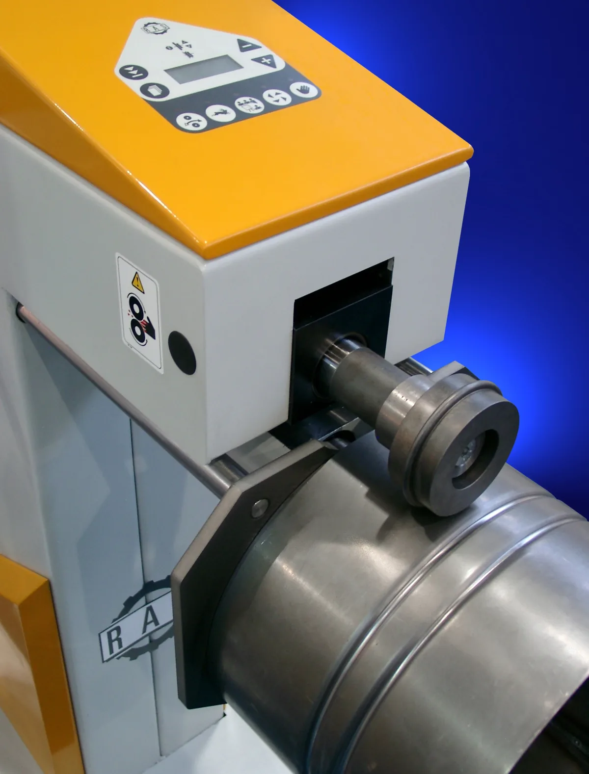
Motorized rotary sheet-metal beading and forming machine with roller die forming circumferential beads in a cylindrical metal tube
Representative rotary tube-beading machine. Photo: Willy Stahl / RAS Reinhardt Maschinenbau GmbH (CC BY-SA 3.0, adapted)

Equipment Category & Mechanical Elements

A specialized tube-forming machine centers on mechanical workpiece retention and controlled axial or rotary deformation.

KINEMATICS

Linear Forming Rams

Axial displacement mechanisms designed to apply controlled linear force, advancing punch tooling into tubular workpieces for expansion, reduction, or flaring.

  • Approach and forming stroke velocity stages
  • Mechanical stop references or linear position feedback
  • Tooling mounts designed for punch replacement
TOOLING

Segmented Clamping Dies

Split collet and jaw assemblies designed to grip the outer tube diameter, distributing holding pressure to support forming forces while minimizing surface marking.

  • Split tool-steel clamping jaws
  • Mechanical toggle locks or hydraulic clamp actuation
  • Keyed die blocks for reproducible alignment
ROTARY

Rotary Forming Spindles

Spinning tool heads designed to roll circumferential beads, sealing grooves, or uniform flares into rotating tubular ends.

  • Variable spindle speed with smooth acceleration
  • Radial tool advance via synchronized cross-slides
  • Coolant or mist lubrication ports at the forming contact zone

Typical Forming Sequence

In tube-end forming machinery, cycles typically follow a deterministic mechanical progression.

STAGE 1

Workpiece Positioning & Clamping

A tube is positioned against a mechanical datum stop, followed by closing of clamping dies to hold the workpiece securely.

STAGE 2

Controlled Tool Advance

The forming ram advances punch tooling along machine guideways, engaging the tube end to initiate controlled metal deformation.

STAGE 3

Geometric Sizing & Dwell

Tooling displacement completes the required end geometry, holding position briefly to stabilize the formed profile.

STAGE 4

Retraction & Workpiece Release

The ram retracts to its resting position and clamping jaws release, allowing the formed tube to be cleared.

OEM Machine Builder vs. Integrator Scope

Machine building stays distinct from engineering consultancy and system integration.

PROFILE

Equipment Builder Focus

A machinery builder focuses on machine bases, drive kinematics, and dedicated tooling, rather than advisory consulting.

BOUNDARIES

Station Builder, Not Plant Integrator

The focus remains on the tube-forming station itself with standard interface handshakes, rather than plant-wide conveyor systems or facility automation.

STRUCTURE

Rigid Base Considerations

Machinery concepts prioritize rigid fabricated machine frames and precision-machined slide surfaces to absorb cyclic forming forces.

Scoping Discussion Considerations

A technical scoping discussion would examine workpiece characteristics and plant interfaces to evaluate application feasibility.

WORKPIECE

Tube Geometry & Material

A scoping discussion would consider tube diameter, wall thickness, material alloy ductility, and yield behavior.

FORMING

Target Profile Geometry

Evaluation would review required expansion ratios, bead profiles, flare angles, and tolerance bands.

FACILITY

Shop Floor & Utility Interface

Review would examine electrical supply, compressed air availability, and physical space requirements for installation.